When you are designing a peripheral device, which is supposed to to communicate with a PC by wire, USB is the clear choice. A USB 1.0 (Full Speed) can be found on every better microcontroller. What if, however, we want to create some peripheral with the need for a much faster communication – say, a USB camera? Professional webcams often use their own custom (ASIC) circuit, which obviously are not intended for general use and therefore are not very interesting for us. Our USB controller should be universal (for general purpose), programmable and therefore it should contain some kind of microcontroller. If you are satisfied with modest bandwidth of USB 2.0 you can choose from variety of interesting general purpose USB controllers (especially from TI and Cypress). For example you can use popular Cypress CY7C68013 (a programmable core here is the good old Intel 8051). However, if you need to transfer a significantly more data, it is time for USB3.0. Although the newer USB3.1 is now the top edge, there is still not so great variety of USB3.0 controllers to choose on the current market. A very interesting programmable USB3.0 controllers seems to be, for example the Cypress EZ-USB FX3 family. The circuits from this family are among other very popular just in USB3.0 digital cameras.
This is of course a high-speed circuit with a BGA housing. So it is somewhat DIY unfriendly and the only way to play with the circuits provide a various developer kits. Today we will take a look at the official developer kit for CYUSB3014 circuit and of course, we will take a peek on the chip itself.
USB 3.0
USB 3.0 is the third generation of USB. Similarly as shifting from USB 1.0 to USB 2.0, also this upgrade brings mainly higher transmission speed – theoretically up to 5 Gbit/s (625 MB/s). Changes, however, are by no means a mere increase in the frequency of transmission. USB 3.0 delivers a completely redesigned physical layer of communication. While USB 2.0 communicates with one bi-directional half-duplex data line, USB 3.0 has two independent, asynchronous communication channels. Communication is thus in a fully duplex mode and this improvement brings a number of benefits.
Thanks to the presence of a separate receive and transmit channel, communication can now be made more efficiently. USB 3.0 does not hold on pooling (periodical host queries), therefore much more of bandwidth can be used to transfer useful data, and a much smaller portion of it serves to just communication overhead. For the same reason, USB 3.0 communication is also more energy efficient. Slave devices can easily manage their sleep mode with asynchronous communication (the slave no longer needs to wake up every 1ms to respond to the host only to tell him about its existence). USB 3.0 also provide a generous power transfer capabilities. This change is particularly reflected on USB 3.0 cabling, which has a significantly enlarged cross section on power wires. Due to the incompatibility of the physical layer of the original USB 2.0 and the new USB 3.0 (and the need for backward compatibility between both), USB 3.0 also includes the original USB 2.0 communication channel.
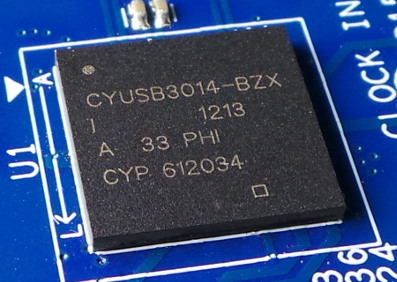
CYUSB3014
CYUSB3014 is a universal programmable USB3.0 controller. The controller also includes support for USB2.0 and USB OTG (On-The-Go) in both host and peripheral roles. The main benefit of the controller, however, is the full-fledged integrated 200MHz ARM core ARM926EJ (ARMv5TEJ architecture) with 512KB SRAM available. The programmable ARM core along with 58 GPIO pins (with configurable voltage levels) and the support of a wide range of classic buses (UART, SPI, I2C, I2S) is what makes the circuit a very universal tool. The CYUSB3014 can be easily connected to a CCD or CMOS image sensor, but also, for example, external RAM memory, any other microcontroller, Arduino, Raspberry Pi and much more. GPIO speed is up to 100Mhz. Such a high toggling speed is a key feature to connection of fast parallel buses of image sensors. The clock source for CYUSB3014 can be an external 19.2, 26, 38.4 or 52 MHz. At 19.2Mhz, however, CYUSB3014 is satisfied with its internal oscillator and only the crystal needs to be connected externally. Of course, high-speed data flowing from GPIO pins to the USB interface does not have to be delayed in the ARM core and can use a sophisticated DMA controller.
CYUSB3KIT-001
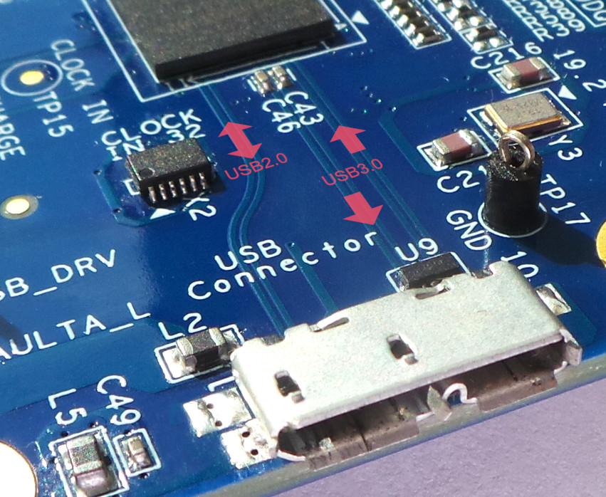
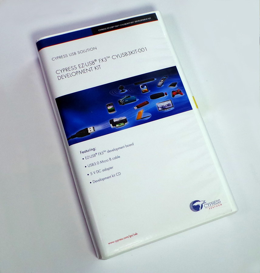
The development kit is called CYUSB3KIT-001 and is manufactured by Cypress itself. The board provides power to the CYUSB3014 chip (using several LDPS TPS76801). Board also distributes GPIO lines from the chip to multiple GPIO headers (Samtec Expansion Connector) and provides a clock source (19.2MHz crystal). The board also contains a MAX3378 logic level converter and an RS232 controller of the MAX13235 line – both circuits cooperates to provide RS232 communication with CYUSB3014, physically realized via a standard 9-pin D-Sub connector. There is also a DC power connector on the board for connecting an external power supply and then, of course, the USB3.0 connector itself in the microUSB style.
Software development for CYUSB3014
All the tools needed to develop firmware for the CYUSB3014 controller can be found at Cypress website . You just need to do free registration before downloading. Both the documentation and the SDK itself (EZ-USB FX3 SDK) are available here. The firmware is by default written in plain C (ANSI C). For convenient development of the software, the SDK offers a modified Eclipse IDE. Compilation and debugging is performed using the Sourcery CodeBench Lite toolchain. The output after compilation (and linking) is a standard * .elf binary file. This is then converted to the * .img memory image using the elf2img tool. *.img file can already be uploaded into the CYUSB3014 RAM (or external FLASH/EEPROM optionally) – again using the tool that is part of Eclipse in the form of a plugin. Physically, the firmware can be uploaded using the JTAG interface (requires a special HW debugger – eg Segger J-Links) or using the USB connection of the PC with the development kit. Preloaded boot loader in CYUSB3014 provides USB communication in this case. However, it is necessary to install the appropriate driver on the PC side (it is again part of the SDK, but it is necessary to install it manually). The SDK also includes several sample projects. Sample projects are set up so that the conversion process to * .img is performed automatically by Eclipse (post-build event). Sample projects also include the appropriate libraries, contain their own makefiles and many other custom settings for the sake of cross compilation on arm926ej-s. New projects are therefore much easier to base on a copy of a existing, sample projects. That way many problems can be avoided.
Perhaps it would be appropriate at the end ot the article to add a little tutorial “How blink LED on the USB3.0 controller” (like a “Hello world” for electronics developers), but exactly this type of tutorial is part of the CYUSB3KIT-001 User Guide on Cypressu web. Thats why I’m saying goodbye just with a photo of flashing LEDs on the controller USB3.0.

Leave a Reply
You must be logged in to post a comment.